An ESR (Equivalent Series Resistance) meter is a device used to measure the equivalent series resistance of capacitors. It’s a valuable tool for checking the health of capacitors in electronic circuits. You can build your own ESR meter by following these instructions:
- Gather necessary components: resistors, capacitors, diodes, inductors, and other elements as described in the circuit diagram.
- Assemble the circuit.
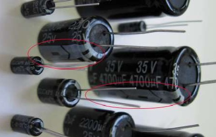
Often, high ESR values are the reason behind the malfunctioning of radio equipment.
Making a Simple Analog ESR Meter
To facilitate the identification of faulty components, we’ll create a simple analog ESR meter. The device operates on the principle of checking resistance in a capacitor at a frequency of 100 kHz. Capacitors with a capacity exceeding a few microfarads will have an ESR value approximately equal to their impedance.
It is generally agreed that high accuracy is not crucial for an ESR meter. In practice, the ESR of a faulty capacitor is significantly higher than that of a functioning one.
Building the ESR Meter
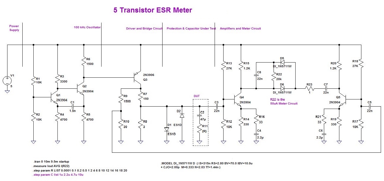
The device’s construction begins with circuit modeling in LTspice. The names of the main functional units can be seen in the diagram.
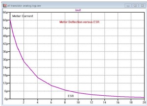
The result of the modeling is a diagram showing how far the needle in the microammeter will deviate, based on the ESR readings.
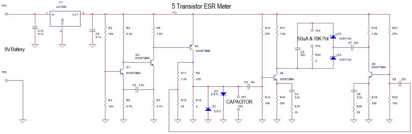
Using the results from the LTspice scheme, you can construct the principal circuit in OrCAD. The device is powered by a 9V supply, and voltage stabilization is achieved using the LM7805 microcircuit. In addition, transistors 2N3904 (n-p-n) and 2N3906 (p-n-p) are used, though any common transistors will suffice. Diodes used are 1N5711. The measuring head current is 50 µA.
The maximum voltage on the terminals of the capacitor being tested is no more than 100 mV, allowing for in-circuit (without desoldering the capacitor) testing.
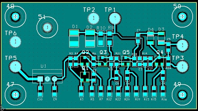
PCB Design and Assembly
Here you can see the layout of the board, which is single-sided and has no jumpers. Efforts are made to use SMD components, although some through-hole components are still needed.
The PCB was manufactured using a CNC machine, with track milling, but LUT or photoresist methods are also viable options.
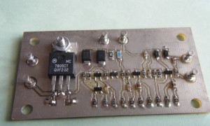
The following image shows the board with components already soldered:
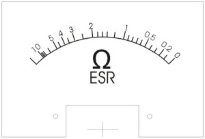
Calibrating the ESR Meter
Calibration is performed using precision resistors with varying resistances in the range of 0.1 – 10 Ohms. The scale is designed using CorelDraw and printed on photo paper.
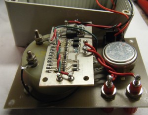
The assembly process is nearing completion. The image below shows the internal side of the ESR meter.
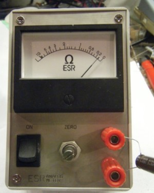
And here is the finished device:
Using the ESR Meter
Before measuring, ensure that the capacitors are discharged. At a supply current of 26 mA, if powered by a “Krona” battery, the device can operate continuously for a day.
Final Steps: Testing Your Device
Test capacitors using the ESR meter to check their condition. A high equivalent series resistance in a capacitor may indicate it is faulty or has reached the end of its life.
Note that building an ESR meter requires knowledge in electronics and circuitry. If you are not an experienced user, it is recommended to purchase a ready-made ESR meter.